
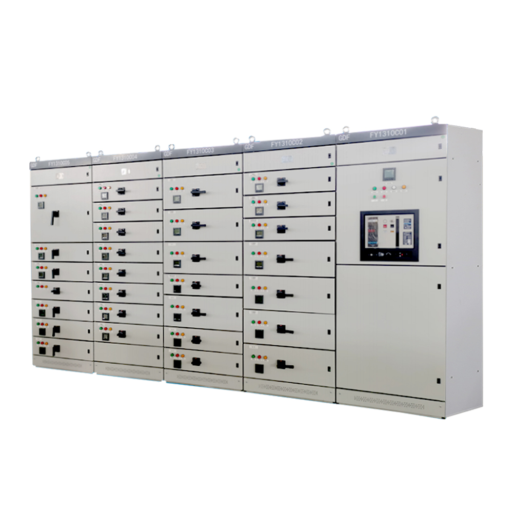
Low-voltage series
GDF
The GDF AC low-voltage fixed-partition switchgear is a new type of switchgear developed in response to market (State Grid Corporation) requirements, drawing on the advantages of MNS and GCS low-voltage switchgear assemblies at home and abroad and adopting high-performance withdrawable or plug-in air circuit breakers, offering safety, reliability and ease of maintenance. This series adopts an independent modular structure design and consists of a horizontal busbar compartment, a vertical busbar compartment, a functional unit compartment and a cable compartment. The compartments are separated and sealed from one another by steel plates or insulating plates, which effectively prevents faults from affecting one another. It is a new product option for AC power distribution systems in power plants, substations, factories and mines. This series complies with the following standards: GB/T 7251.12 "Low-voltage switchgear and controlgear assemblies - Part 2: Power switchgear and controlgear assemblies"; IEC 60439 "Low-voltage switchgear and controlgear assemblies".
Request a quotePlease provide your operating conditions, quantity and required connection or output.
Technical details
Specifications from source material
The GDF AC low-voltage fixed-partition switchgear is a new type of switchgear developed in response to market (State Grid Corporation) requirements, drawing on the advantages of MNS and GCS low-voltage switchgear assemblies at home and abroad and adopting high-performance withdrawable or plug-in air circuit breakers, offering safety, reliability and ease of maintenance. This series adopts an independent modular structure design and consists of a horizontal busbar compartment, a vertical busbar compartment, a functional unit compartment and a cable compartment. The compartments are separated and sealed from one another by steel plates or insulating plates, which effectively prevents faults from affecting one another. It is a new product option for AC power distribution systems in power plants, substations, factories and mines. This series complies with the following standards: GB/T 7251.12 "Low-voltage switchgear and controlgear assemblies - Part 2: Power switchgear and controlgear assemblies"; IEC 60439 "Low-voltage switchgear and controlgear assemblies".
- Rated operational voltage (Ue)
- V 400, 380
- Rated operational current (In)
- A ≤ 4000
- Rated frequency (Fn)
- Hz 50/60
- Rated insulation voltage (Ui)
- V 660, 690
- Rated short-time withstand current (Icw)
- kA 65
- Rated peak withstand current (Icw)
- kA 143
- Rated impulse withstand voltage (Uimp)
- kV 8
- Overvoltage category
- IV
- Pollution degree
- 3
- Clearance
- ≥ 10 mm
- Creepage distance
- ≥ 12.5 mm
- Degree of protection
- (customizable on special request) IP30, IP40
- Incoming and outgoing feeder cabinets
- Height (mm) 2200
Full product details
Overview
The GDF AC low-voltage fixed-partition switchgear is a new type of switchgear developed in response to market (State Grid Corporation) requirements, drawing on the advantages of MNS and GCS low-voltage switchgear assemblies at home and abroad and adopting high-performance withdrawable or plug-in air circuit breakers, offering safety, reliability and ease of maintenance. This series adopts an independent modular structure design and consists of a horizontal busbar compartment, a vertical busbar compartment, a functional unit compartment and a cable compartment. The compartments are separated and sealed from one another by steel plates or insulating plates, which effectively prevents faults from affecting one another. It is a new product option for AC power distribution systems in power plants, substations, factories and mines. This series complies with the following standards: GB/T 7251.12 "Low-voltage switchgear and controlgear assemblies - Part 2: Power switchgear and controlgear assemblies"; IEC 60439 "Low-voltage switchgear and controlgear assemblies".
Operating environment
1. Ambient air temperature not higher than +40°C and not lower than -5°C. The average temperature within 24 h shall not exceed +35°C. 2. For indoor installation and use; the altitude of the installation site shall not exceed 2000 m. 3. Relative humidity of the ambient air shall not exceed 50% at a maximum temperature of +40°C; higher relative humidity is permissible at lower temperatures, for example 90% at +20°C, but occasional condensation may occur due to temperature changes. 4. During installation, the inclination from the vertical shall not exceed 5°. 5. The equipment shall be installed in locations free from severe vibration and shock, and where electrical components are not readily subject to corrosion. *Note: Special requirements can be resolved through consultation with the manufacturer.
Technical parameters
Rated operational voltage (Ue): V 400, 380; Rated operational current (In): A ≤ 4000; Rated frequency (Fn): Hz 50/60; Rated insulation voltage (Ui): V 660, 690; Rated short-time withstand current (Icw): kA 65; Rated peak withstand current (Icw): kA 143; Rated impulse withstand voltage (Uimp): kV 8; Overvoltage category: IV; Pollution degree: 3; Clearance: ≥ 10 mm; Creepage distance: ≥ 12.5 mm; Degree of protection: (customizable on special request) IP30, IP40.
Dimensions
Incoming and outgoing feeder cabinets: Height (mm) 2200; Width (mm) 600, 800, 1000; Depth (mm) 600, 800, 1000.
Product features
Main busbars: Copper busbars generally use copper with a content of 99.9%; prototypes are manufactured according to this specification and have passed type tests. Based on pre-calculated data, the busbars are bent with a busbar processing machine; the bending angle shall not be too small for the busbar specification, no cracks are permitted at the bends, and the bend heights of horizontally arranged busbars shall be uniform. Busbar ends are embossed, and after embossing a label is applied to indicate phase sequence. Structural features: The product is self-supporting and installed vertically on the floor; its basic frame is assembled from C-shaped steel. The cabinet components are designed on the modular principle, with mounting holes on a 20 mm or 25 mm module. The degree of commonality is relatively high; depending on the system scheme, the cabinet is assembled from individual component compartments and the basic cabinet with bolts. The interior is divided into areas such as horizontal busbars, vertical busbars, cable area and functional unit area. Cables can be routed out from the top or bottom of the cabinet; each area is effectively isolated by steel plates, and the functional units are also isolated from one another, so they do not interfere with each other, limiting the scope of fault effects. The GDF cabinet uses advanced electrical components from home and abroad. Air circuit breakers are withdrawable type with fixed horizontal rear connections; molded case circuit breakers are plug-in type with front or rear connections, so that branch busbars and the main busbar are directly fixed and connected, reducing the disadvantages of all-drawer cabinets caused by an intermediate mechanism (plug-in connectors) (poor interchangeability, complex machining, more chances of failure). This cabinet combines the advantages of drawer cabinets and fixed cabinets, with high operational reliability. Owing to the use of advanced switches and high-quality accessories, the volume is greatly reduced. Components are easy to replace; only the switch body needs to be replaced (spare switch components are easier and more economical than spare conventional drawers), with no need to shut down the system. Heat dissipation during operation is good: the upper and lower ends of the cabinet have ventilation slots. When components inside heat up, the heat rises and is discharged through the upper slots, while cool air is continuously drawn in through the lower slots, achieving heat dissipation. Corrosion protection: The cabinet is finished by electrostatic epoxy powder coating, and other metal parts are corrosion-resistant.